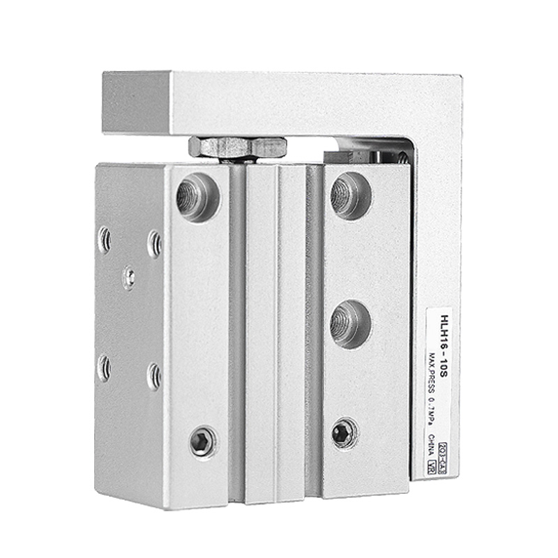
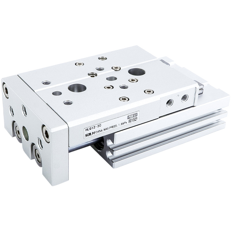
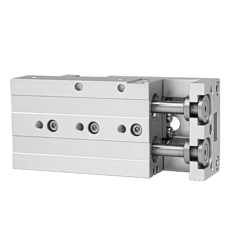
SOLH HLS / HLSL twin-shaft slide cylinders adopt line-contact cross roller guides, delivering much higher rigidity, repeat positioning accuracy and eccentric load resistance than HLQ ball guide models. Two variants are available: standard HLS with side-mounted compact cylinder for medium-small loads without severe offset; symmetrical HLSL with centered cylinder and dual parallel rollers for heavy loads, large eccentric torque and ultra-precision demands. Bore sizes cover 6–25 mm and strokes 10–150 mm. Twin piston rods provide powerful thrust and anti-torsion performance, while built-in floating joints eliminate lateral deflection stress. The base supports 3-direction mounting holes, the slide carriage reserves multi-surface fixture threads & positioning pins, and magnetic ring plus sensor slots come as standard. Adjustable air buffers, hydraulic shock absorbers and external mechanical stops are optional accessories. Operating temperature ranges from -20℃ to 70℃. Widely used in semiconductor, medical automation, machine tool jigs and other heavy-duty ultra-precision transfer & clamping positioning stations.
SOLH HLS / HLSL series twin-shaft precision slide cylinder adopts cross roller linear guide as core guiding component. Compared with HLQ recirculating ball slide cylinders, it delivers far higher rigidity, superior repeat positioning accuracy and stronger resistance to eccentric side loads, perfectly matching heavy-load, ultra-precision assembly and positioning automation processes.
Series Classification: HLS VS HLSL
-- HLS Standard Type: Cylinder body installed on one side of slide carriage, compact overall width. Suitable for limited installation space, medium-small load conditions without obvious eccentric offset load.
-- HLSL Symmetrical Type: Cylinder centered between two parallel cross roller guides, uniform force distribution, greatly enhanced rigidity and heavy load capacity. First choice for heavy load, eccentric load and ultra-high precision working scenarios.
Core Technical Specification Table
Parameter Item
Specification Details
Guiding Mechanism
Cross roller linear guide (line contact roller type)
Operation Type
Double acting reciprocating
Bore Sizes (mm)
6, 8, 12, 16, 20, 25
Standard Stroke Options (mm)
10, 20, 30, 40, 50, 75, 100, 125, 150
Operating Pressure Range
0.15 ~ 0.7 MPa
Proof Test Pressure
1.2 MPa
Operating Temperature
-20℃ ~ 70℃ (no internal icing)
Piston Travel Speed
50 ~ 500 mm/s
Stroke Tolerance
Stroke ≤100mm: +1.0mm; Stroke >100mm: +1.5mm
Air Port Thread Spec
Bore 6/8/12: M5×0.8; Bore 16/20/25: PT1/8
Magnetic Ring
Built-in as standard (suffix S), compatible with CMSH / DMSH magnetic reed switches
Structural & Core Performance Advantages
1. Cross Roller Linear Guide (Roller Line Contact Design)
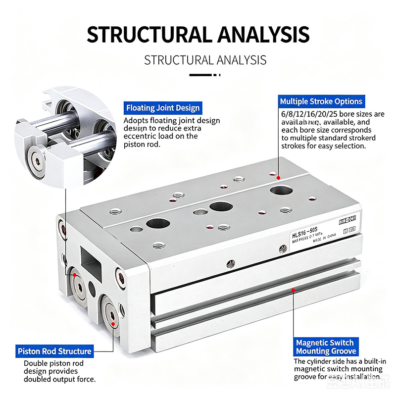
-- Line contact bearing structure provides extreme rigidity, outstanding straightness and anti-rotation precision, strong impact resistance and stable operation under heavy load. Integrated one-piece guide carriage design with ultra-low friction, ultra-smooth movement and extended service cycle.
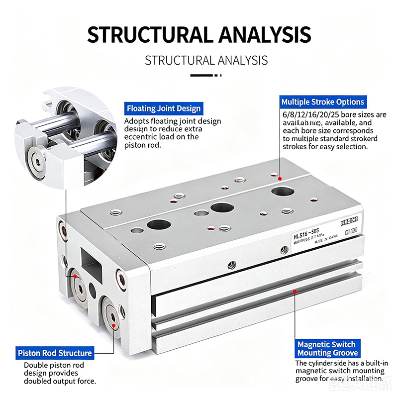
2. Built-In Floating Joint
-- Elastic floating connection between piston rod and slide platform offsets lateral force and eccentric torque, avoiding piston rod deflection and overload damage.
3. Twin Parallel Piston Rods
-- Double thrust output, excellent anti-torsion performance, maintains high positioning accuracy under loaded state.
4. Multi-Directional Universal Mounting
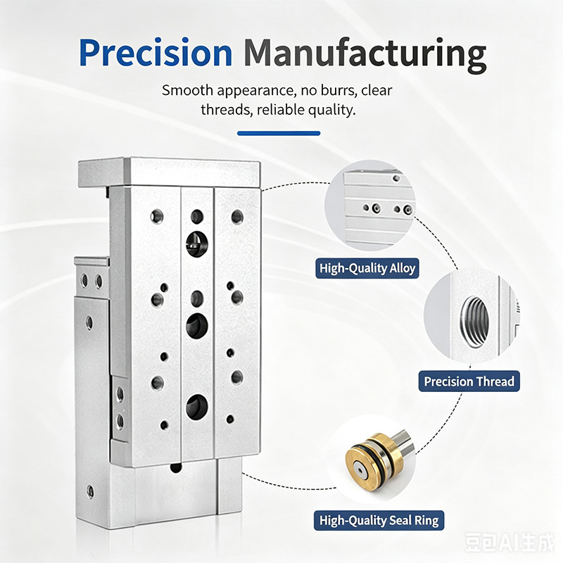
-- Tapped mounting holes machined on bottom, front and side surfaces for 3-direction installation; precision locating pin holes pre-machined on base for rapid accurate positioning.
5. 3-Side Tooling Mount Surfaces
-- Tapped fixture mounting holes on slide top and front face, locating pin holes on slider top plane to guarantee repeatable jig positioning precision.
6. Pre-Machined Sensor Installation Grooves
-- Standard sliding slots on cylinder side for flexible installation and position adjustment of magnetic switches.
7. Diversified Buffer & Limit Stop Options
-- Fixed air buffer, adjustable air buffer (A/AS/AF), hydraulic shock absorber buffer (B/BF) and multiple external mechanical limit stop blocks are optional combinations.
Standard Model Naming Rule
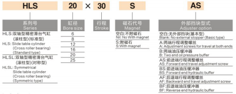
1. Example Model: HLS20×30SAS
-- HLS = Standard side cylinder series; HLSL = Symmetrical centered high-rigidity series
-- 20 = Cylinder bore diameter (mm)
-- 30 = Rated stroke length (mm)
-- S = Built-in permanent magnetic ring (standard factory configuration)
-- A = Adjustable air buffer on both ends
AS = Adjustable air buffer only on forward stroke end
AF = Adjustable air buffer only on return stroke end
-- B = Hydraulic oil buffer on both ends
BF = Hydraulic oil buffer only on return stroke end
For inquiries about low voltage switchgear, high voltage insulators, high voltage earthing switch or price list, please leave your email to us and we will be in touch within 24 hours.
We use cookies to offer you a better browsing experience, analyze site traffic and personalize content. By using this site, you agree to our use of cookies.Privacy Policy