Electrical contact resistance is a critical factor affecting power loss, temperature rise, and connection reliability in high voltage switchgear. A properly designed Tulip Contact helps reduce resistance through high-conductivity copper alloy contact fingers, silver or gold plating, and a spring-loaded elastic structure that maintains consistent contact pressure. In this article, we explain how these design features improve current transmission, what causes contact resistance to increase, and how Richge's YCT, ZF10-126, and ZF10-252(GIS) series support different switchgear connection requirements.
In high voltage switchgear, electrical current passes through several conductive interfaces, including busbars, terminals, circuit breaker connections, and plug-in contacts. Each connection introduces a certain amount of electrical resistance. When contact resistance becomes excessive, more electrical energy is converted into heat at the connection point.
We pay particular attention to this issue when evaluating switchgear contact components because a connection can appear mechanically secure while still having an unfavorable electrical contact condition.
Several factors can increase electrical contact resistance:
The relationship between resistance and heating can be expressed using the formula:
P = I²R
Where P represents power loss in watts, I is current in amperes, and R is contact resistance in ohms.
For example, if a connection carries 1,000A and has a contact resistance of 10 micro-ohms, its theoretical contact heating is:
P = 1,000² × 0.00001 = 10W
If resistance increases to 20 micro-ohms under the same current, the heat generated rises to 20W. This illustrates why even a relatively small increase in contact resistance can matter in high-current switchgear connections.
Actual temperature rise also depends on heat dissipation, conductor geometry, ambient temperature, and installation conditions. Therefore, resistance measurements and temperature-rise testing should be evaluated together.
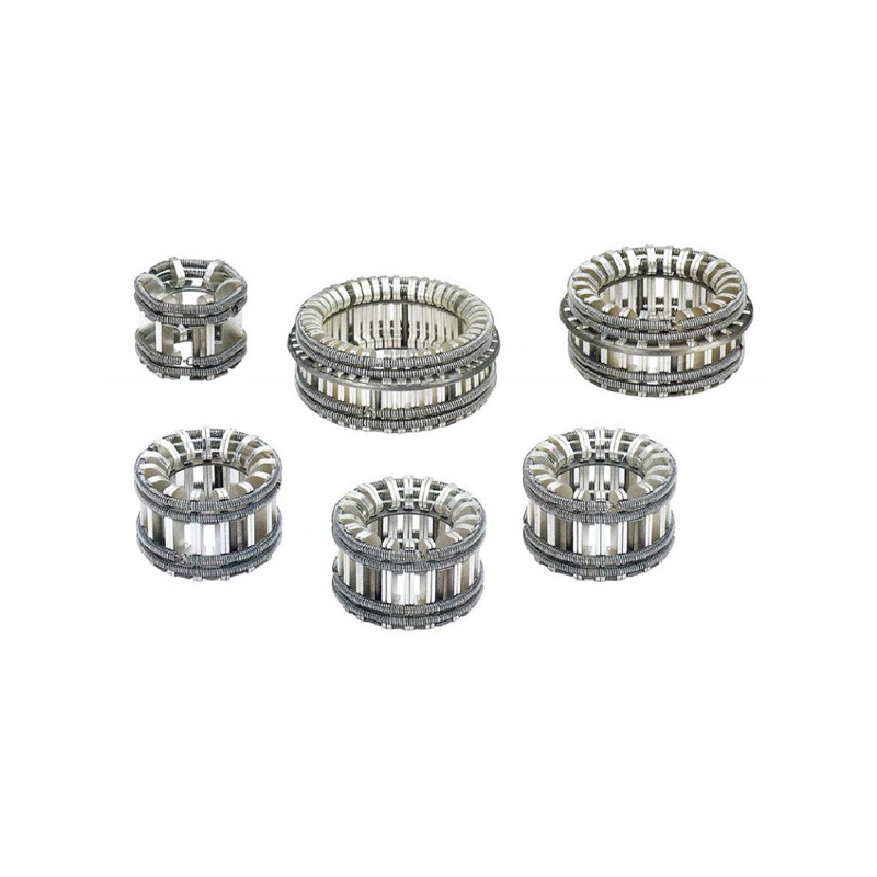
A Tulip Contact uses multiple elastic metal contact fingers arranged around a central opening. The contact fingers resemble flower petals, which is where the product gets its name. When a matching cylindrical conductor or contact stud is inserted, the fingers flex outward and apply pressure around the mating surface.
We consider this multi-finger arrangement one of the main reasons tulip contacts are widely used in plug-in connections for switchgear. Instead of relying on one rigid contact point, the structure creates multiple parallel electrical contact paths.
Each contact finger contributes to the overall conductive path. When the fingers have consistent geometry and contact pressure, current can be distributed across multiple contact points rather than concentrated in one localized area.
This arrangement helps reduce localized resistance and supports more uniform current transmission. However, the benefit depends on the number of fingers, their dimensions, surface condition, and the quality of the mating connection.
In actual switchgear manufacturing, small dimensional deviations can occur between the mating conductor and the contact assembly. A rigid connection may be more sensitive to these differences.
The elastic contact fingers in a Tulip Contact provide a degree of mechanical compensation. When the mating conductor is inserted, the fingers adjust to its dimensions and maintain contact with the surrounding surface.
This is particularly useful in withdrawable switchgear, where reliable electrical connections must be established after repeated insertion and withdrawal operations.
A multi-finger design also provides several contact points around the mating conductor. If one contact area experiences minor surface wear, the remaining contact fingers can continue contributing to the overall connection, provided the assembly remains within its design limits.
For this reason, we recommend evaluating the complete contact assembly rather than looking only at the material of an individual contact finger.
Material selection directly affects electrical conductivity, mechanical strength, wear resistance, and long-term connection performance. Richge's Tulip Contact product description specifies a highly conductive copper alloy contact sheet with silver or gold plating options.
These material choices serve different purposes in the contact assembly.
| Material or Treatment | Main Function | Performance Consideration |
|---|---|---|
| Copper Alloy | Provides the main conductive contact structure | Combines electrical conductivity with mechanical strength and elasticity |
| Silver Plating | Improves the electrical contact surface | Supports low contact resistance and good conductivity |
| Gold Plating | Provides a corrosion-resistant contact surface | Useful where surface stability and oxidation resistance are priorities; application suitability depends on electrical duty |
| Spring Material | Maintains clamping force on the contact fingers | Spring characteristics influence contact pressure and mechanical durability |
Silver has high electrical conductivity and is widely used on electrical contact surfaces. In a silver-plated Tulip Contact, the plating provides a conductive interface between the elastic contact fingers and the mating conductor.
Surface condition is especially important in high-current applications. Scratches, contamination, uneven plating, and excessive wear may affect the actual contact area and increase resistance over time.
We recommend considering plating thickness and coverage as part of the product specification rather than treating silver plating as a simple yes-or-no requirement.
Gold plating offers good resistance to oxidation and corrosion. It may be appropriate for certain specialized contact applications where surface stability is important. However, gold is not automatically the best choice for every high-current switchgear connection. Current rating, contact pressure, operating environment, cost, and electrical duty must all be considered.
The final plating selection should therefore follow the switchgear manufacturer's technical requirements and the intended operating conditions.
Even when the contact material has good electrical conductivity, insufficient mechanical pressure can increase the resistance at the mating interface. This is why the spring mechanism is an important part of a Tulip Contact.
Richge's product structure uses an internal spring system to apply a uniform clamping force to the contact fingers. When the mating conductor enters the contact assembly, the spring mechanism helps maintain pressure between the conductive surfaces.
There are three practical benefits:
Uniform pressure helps the contact fingers maintain stable engagement with the mating conductor. Uneven pressure may cause some fingers to carry more current than others, potentially creating localized heating.
The elastic mechanism allows the contact assembly to accommodate small dimensional differences between mating components. This helps maintain electrical continuity without requiring every contact interface to have perfectly identical dimensions.
Switchgear may experience mechanical vibration and shock during operation or transportation. A properly designed spring mechanism helps maintain contact engagement under specified mechanical conditions.
However, spring force should not simply be increased as much as possible. Excessive pressure can increase insertion force and accelerate mechanical wear, while insufficient pressure may lead to unstable contact conditions. The appropriate spring design needs to balance electrical performance and mechanical requirements.
A low-resistance connection is the result of several design and manufacturing factors working together. When we evaluate a Tulip Contact, we recommend checking the following parameters:
| Performance Factor | Effect on Contact Resistance | What to Check |
|---|---|---|
| Contact Material | Influences the conductivity of the current path | Copper alloy grade and material consistency |
| Plating Quality | Affects the conductive interface and surface durability | Plating material, thickness, coverage, and adhesion |
| Spring Force | Influences the real contact area and connection stability | Clamping force and elastic recovery |
| Contact Finger Geometry | Affects current distribution and mechanical engagement | Finger dimensions, spacing, and alignment |
| Mating Dimensions | Determines whether the contact fingers engage correctly | Conductor diameter, insertion depth, and dimensional tolerances |
| Surface Condition | Oxidation and contamination can increase resistance | Surface cleanliness, wear, and corrosion |
Manufacturing consistency is equally important. Precision stamping, machining, and assembly help control the geometry of individual contact components. If contact fingers vary significantly in size or spring response, the final assembly may not distribute pressure evenly.
For switchgear manufacturers, we recommend confirming contact resistance through appropriate testing on the assembled connection. A material specification alone cannot establish the actual resistance of the complete contact interface.
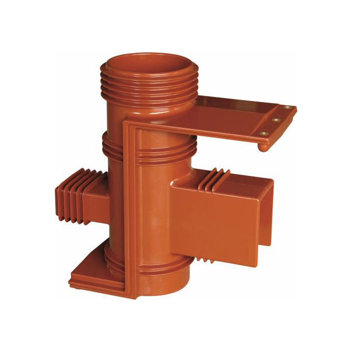
Tulip contacts are commonly used where a removable or plug-in electrical connection is required. Their multi-finger structure makes them suitable for applications that need reliable electrical engagement together with convenient installation and maintenance.
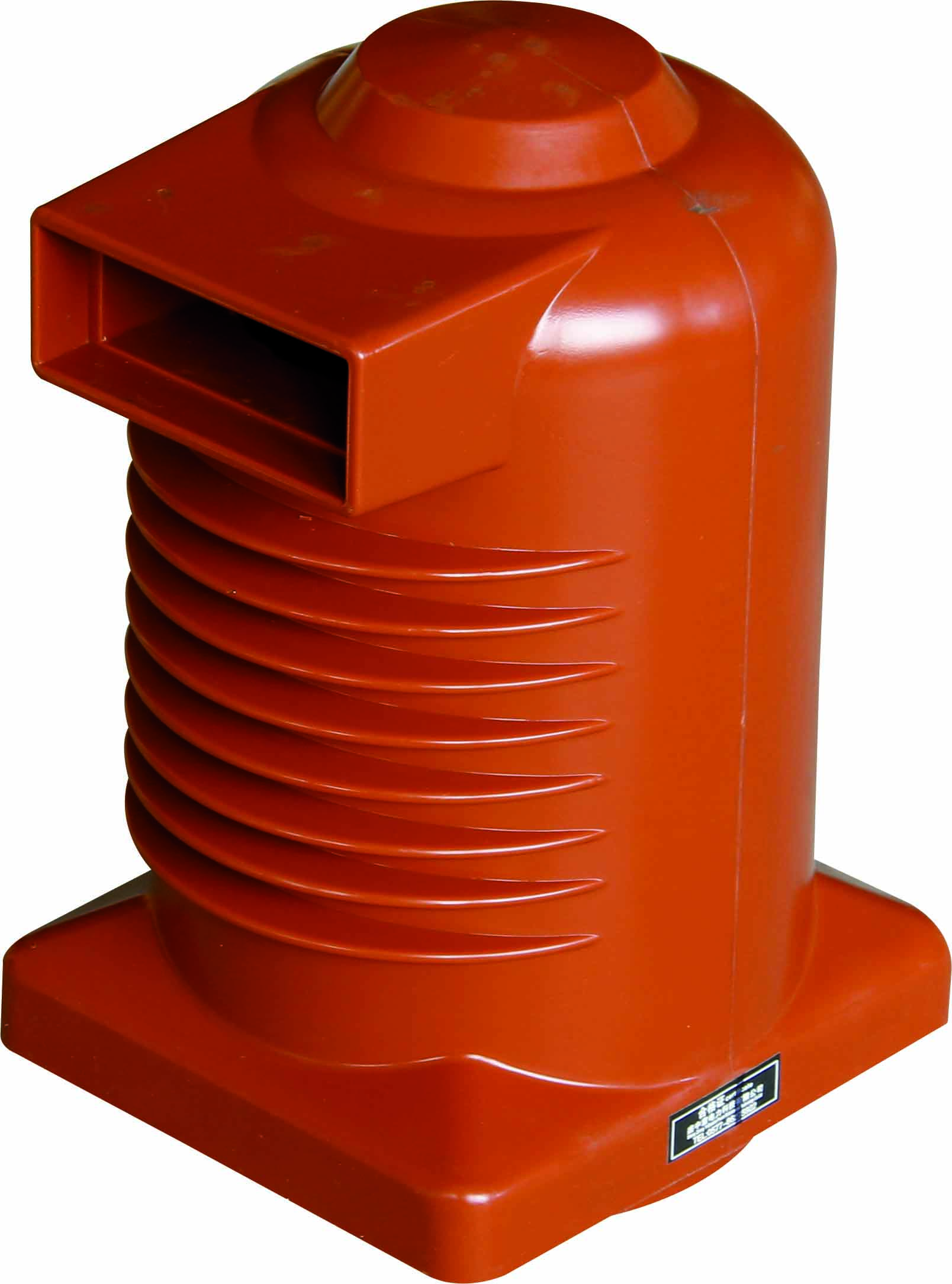
The YCT series is one of the product configurations listed in Richge's Tulip Contact range. Its outline and assembly dimensions should be matched with the corresponding switchgear connection structure. When replacing an existing contact, we recommend checking the original drawing and mating conductor dimensions rather than selecting a replacement based only on its product name.
The ZF10-126 series is included in Richge's product dimension references. For this type of high voltage switchgear application, contact geometry, assembly clearance, mating dimensions, and electrical requirements should be reviewed together to ensure proper integration.
Richge also provides an outline and assembly dimension reference for the ZF10-252(GIS) series. GIS equipment has specific space and insulation requirements, so contact selection must follow the equipment manufacturer's design drawings and electrical specifications.
For all three series, the key engineering task is to ensure that the contact assembly matches the mating conductor and the operating conditions of the complete switchgear system. The product outline drawing is an important starting point, but it does not replace electrical performance verification.
You can view the available configurations and product information on the Richge Tulip Contact product page.
Even a well-designed contact assembly can experience performance changes after extended operation. Dust, oxidation, mechanical wear, and repeated insertion cycles may affect the contact surface and spring performance.
We recommend establishing a maintenance procedure based on the switchgear manufacturer's instructions and the actual operating environment.
Check the contact fingers and mating conductor for discoloration, contamination, pitting, and visible wear. Uneven surface marks may indicate poor alignment or inconsistent contact pressure.
Use an approved, non-corrosive cleaning method suitable for the contact material and plating. Avoid abrasive tools or aggressive chemicals that may damage the conductive coating.
Inspect the spring mechanism for deformation, fatigue, corrosion, or loss of clamping force. If the contact fingers no longer maintain the required pressure, replacing the affected assembly may be necessary.
Use an appropriate low-resistance measurement instrument to check the connection according to the equipment manufacturer's testing procedure. Compare the measured value with the applicable design or maintenance acceptance criteria and previous inspection records.
Some switchgear designs require a specified contact lubricant to reduce friction and protect contact surfaces. However, not every lubricant is suitable for every plating material or electrical application. We recommend following the equipment manufacturer's instructions and avoiding excessive grease application.
If contact resistance exceeds the permitted limit, the plating is seriously damaged, or the spring mechanism has lost its elasticity, the contact assembly should be evaluated for replacement. Continuing to operate a connection with deteriorated contact conditions may increase the risk of overheating.
For switchgear manufacturers and power engineering projects, product selection should begin with the actual electrical and mechanical requirements rather than general product descriptions.
We recommend preparing the following information before requesting a quotation or technical evaluation:
| Selection Item | Information to Confirm |
|---|---|
| Switchgear Model | YCT, ZF10-126, ZF10-252(GIS), or other equipment model |
| Rated Voltage | System voltage and applicable insulation requirements |
| Rated Current | Continuous current and relevant overload or short-circuit requirements |
| Contact Material | Copper alloy grade and required mechanical properties |
| Surface Treatment | Silver plating, gold plating, or another specified finish |
| Assembly Dimensions | Outer diameter, inner diameter, insertion depth, and mounting dimensions |
| Spring Requirements | Clamping force, elastic behavior, and mechanical durability |
| Operating Conditions | Temperature, vibration, installation environment, and maintenance requirements |
For replacement projects, an original drawing or physical sample is particularly useful. We recommend checking the mating conductor as well, because copying the dimensions of a worn contact without verifying its counterpart may reproduce an existing fitting problem.
Richge supports OEM and ODM cooperation for its Tulip Contact products. Customers can discuss product dimensions, assembly requirements, and material or surface treatment options according to their project specifications.
Our company, Ningbo Richge Technology Co., Ltd., was established in 2021 by integrating industrial resources dating back to 1987. With 45,000 square meters of land and 100,000 square meters of construction area, we have over 30 years of industry experience in high and low voltage electrical products and industrial automation. We provide supporting products and procurement services for power engineering, industrial automation, and high-end equipment manufacturing customers in more than 30 countries.
For related product information and technical discussions, visit Richge's Tulip Contact page.
A Tulip Contact uses multiple elastic copper alloy contact fingers to create parallel conductive paths around a mating conductor. Its spring mechanism maintains contact pressure, while silver or gold plating provides a suitable conductive surface. These features help establish a stable, low-resistance electrical connection when the assembly is correctly designed and installed.
Silver has high electrical conductivity and is commonly used to improve the performance of electrical contact surfaces. Silver plating helps provide a conductive interface between mating components. Its effectiveness over time also depends on plating thickness, surface condition, contact pressure, and insertion frequency.
Not necessarily. More contact fingers can provide additional parallel current paths, but the actual benefit depends on finger dimensions, contact pressure, material, and current distribution. An appropriate finger arrangement should be designed around the rated current and mechanical requirements of the switchgear.
Common causes include excessive contact resistance, insufficient spring pressure, oxidation, damaged plating, poor alignment, contamination, and overloading. Incorrect insertion depth or an incompatible mating conductor can also contribute to localized heating.
The spring mechanism applies clamping force to the elastic contact fingers. This helps maintain engagement with the mating conductor, compensates for minor dimensional variations, and supports connection stability under specified mechanical conditions.
Richge's product information includes YCT, ZF10-126, and ZF10-252(GIS) series. Customers should confirm the corresponding outline drawings, assembly dimensions, and electrical requirements before selecting a configuration.
Yes. Richge supports OEM and ODM cooperation. Customers can provide technical drawings, product samples, or project requirements for discussions about dimensions, materials, surface treatments, and assembly compatibility.
There is no universal maintenance interval for every switchgear installation. Inspection frequency should depend on the equipment manufacturer's recommendations, operating environment, switching frequency, and maintenance history. Contact surfaces, spring elasticity, and measured contact resistance should be included in the inspection.
Reducing electrical contact resistance requires more than selecting a conductive metal. The contact structure, material quality, surface treatment, spring pressure, dimensional accuracy, and maintenance condition all influence the performance of a Tulip Contact.
For high voltage switchgear, Richge focuses on contact solutions that combine multi-piece elastic copper alloy fingers, silver or gold surface treatments, and spring-loaded contact structures. Our YCT, ZF10-126, and ZF10-252(GIS) product configurations provide different dimensional references for equipment integration.
Whether you are developing new switchgear or replacing existing contact components, we recommend starting with the equipment drawing, mating conductor dimensions, rated current, and required electrical performance. This approach makes it easier to identify a suitable Tulip Contact and maintain reliable electrical connections throughout the equipment's service life.